A lot of making goes on in this community these days, but sometimes you’ve just gotta do some old fashioned hacking. You might have grabbed an old Speak and Spell that you want to repurpose as an interface for a horrifyingly rude chatbot, or you’ve got a calculator that is going to become the passcode keypad for launching your DIY missiles. You want to work with the original hardware, but you need to figure out how to interface all the buttons yourself.
Thankfully, this is usually an easy job. The vast majority of buttons and keypads and keyboards are all implemented pretty much the same way. Once you know the basics of how to work with them, hooking them up is easy. It’s time to learn about key matrixes!
Wire ‘Em Up
Imagine you have a piece of consumer hardware, like a desk phone or an old control panel or something. You’d like to hook up a microcontroller to read all the buttons. Only, there’s 10, or 20, or 100 buttons… and your microcontroller just doesn’t have that many I/O pins! If you’re only familiar with hooking up a couple of push buttons to a couple of pins on an Arduino with some pull-up resistors, this can feel like an overbearing limitation. However, thankfully—there is a better way!
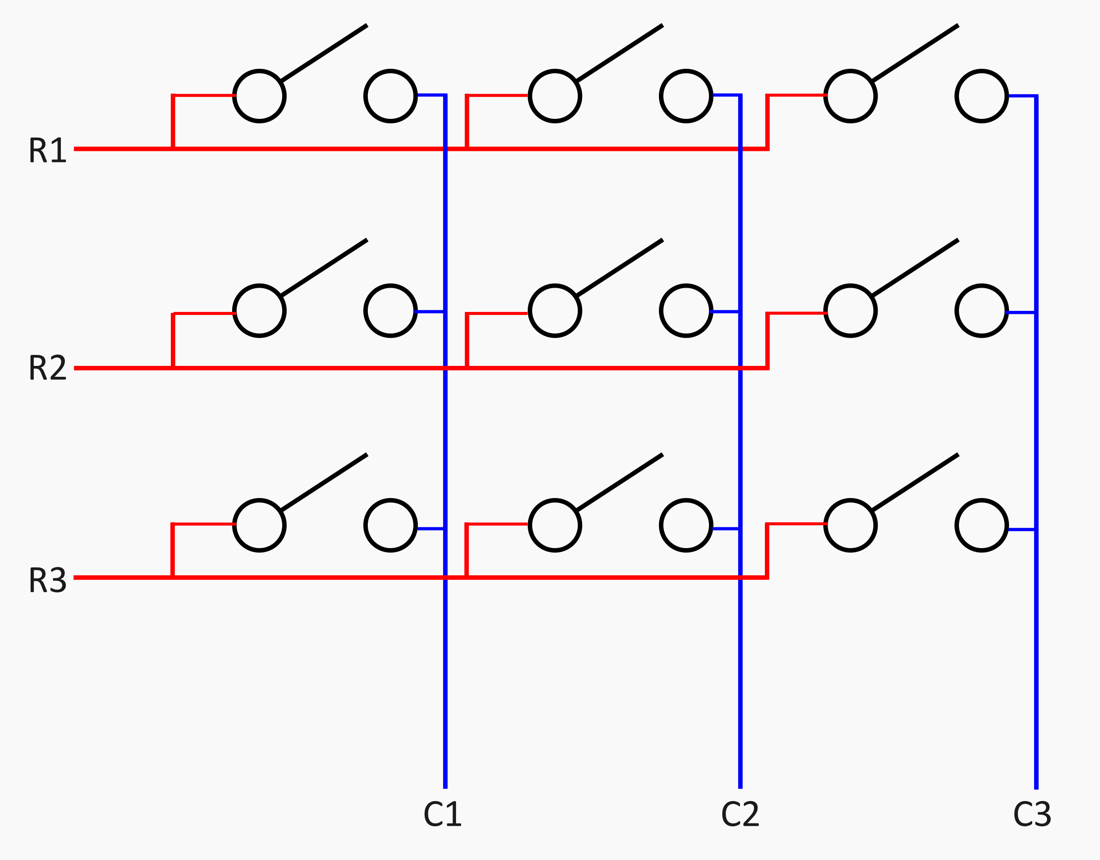
Enter the key matrix. It’s a very simple way of hooking up more buttons to less I/O pins. Imagine, for example, a nine-digit keypad, arranged in a 3 x 3 square. Assign three pins for columns, and three pins for rows. Each button in the keypad is hooked up to one row pin and one column pin. You can then, for example, energize each row pin in turn with a high output on a microcontroller, and detect whether any of the column pins go high by setting them to inputs. Do this quickly enough, and you can detect the state of all nine buttons with just six pins. In fact, the technique is generalizable—for n pins, you can address (n/2)2 buttons. For six pins, that’s nine buttons.
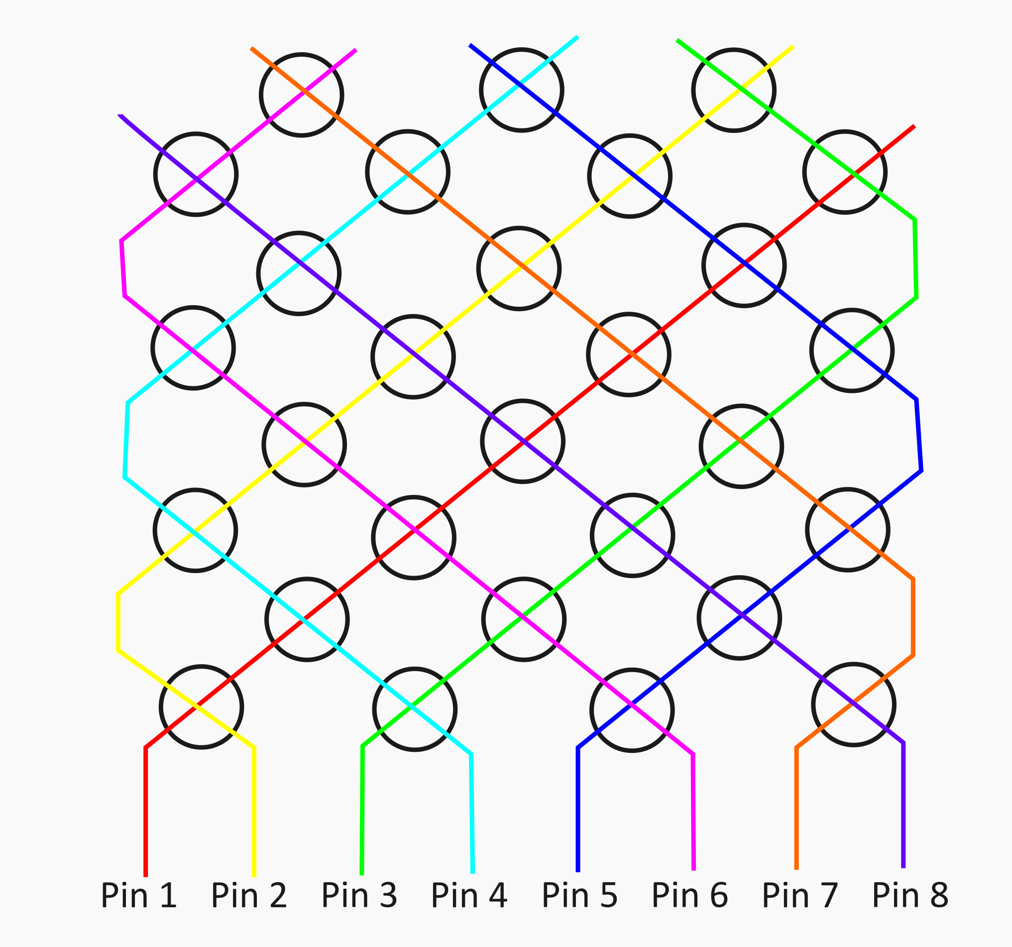
You can even take it further, if you abandon the concept of a grid-like row-and-column layout. You can instead take six pins, for example, treating each one as its own “row.” You then place a button between it and every other pin, doing the same for each following pin in turn. You can then energize pin 1, while scanning pins 2 through six to see which buttons were pressed, and so on through the rest of the pins. This will net you a higher amount of buttons per pin—(n2-n)/2, in fact. For our six pin example, you could address 15 buttons this way.
When you expect multiple button presses at a time, you should add diodes into the button matrix to prevent current paths taking unexpected directions, and you might be lucky enough to find that your device already has them. There are even more advanced techniques, like Charlieplexing, that can address n2 – n switches, but you’re less likely to come across this in the wild except for pin-constrained LED circuits.
These techniques are commonly referred to as multiplexing, and you’ll find it in all sorts of places. Everything from TV remotes to desktop calculators use this sort of technique to address many buttons without requiring lots of individual I/O pins.
Once you’re aware of this, it generally becomes straightforward to open up any such piece of hardware and figure out how the buttons work. All you need to do is hunt down the traces that connect from button to button, and slowly map out how they’re all connected. Mapping out the board can be challenging, though, because designers don’t always make the traces easy to follow. While something like a keypad may be logically connected in a grid-type layout, for example, it might not actually look like that on the PCB. The traces might be going every which way, complicating your efforts to figure out what’s connected to what.
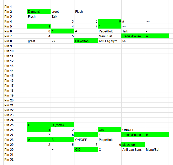
A multimeter set to continuity mode is a great tool for this work. It lets you tap around a PCB to figure out which side of each button is connected to which other buttons, allowing you to figure out how the matrix is laid out. For example, if you were working with a phone keypad, you might start by putting a multimeter lead on one of the contacts of the “1” button. You might then find that it’s connected to one side of the buttons for 3, 5, 9, and *. You can then probe the other side of each of those buttons to find out what they’re connected to as well. Put all this data into a spreadsheet, and you’ll eventually see which two pins you need to check to determine the status of any button on the keypad.
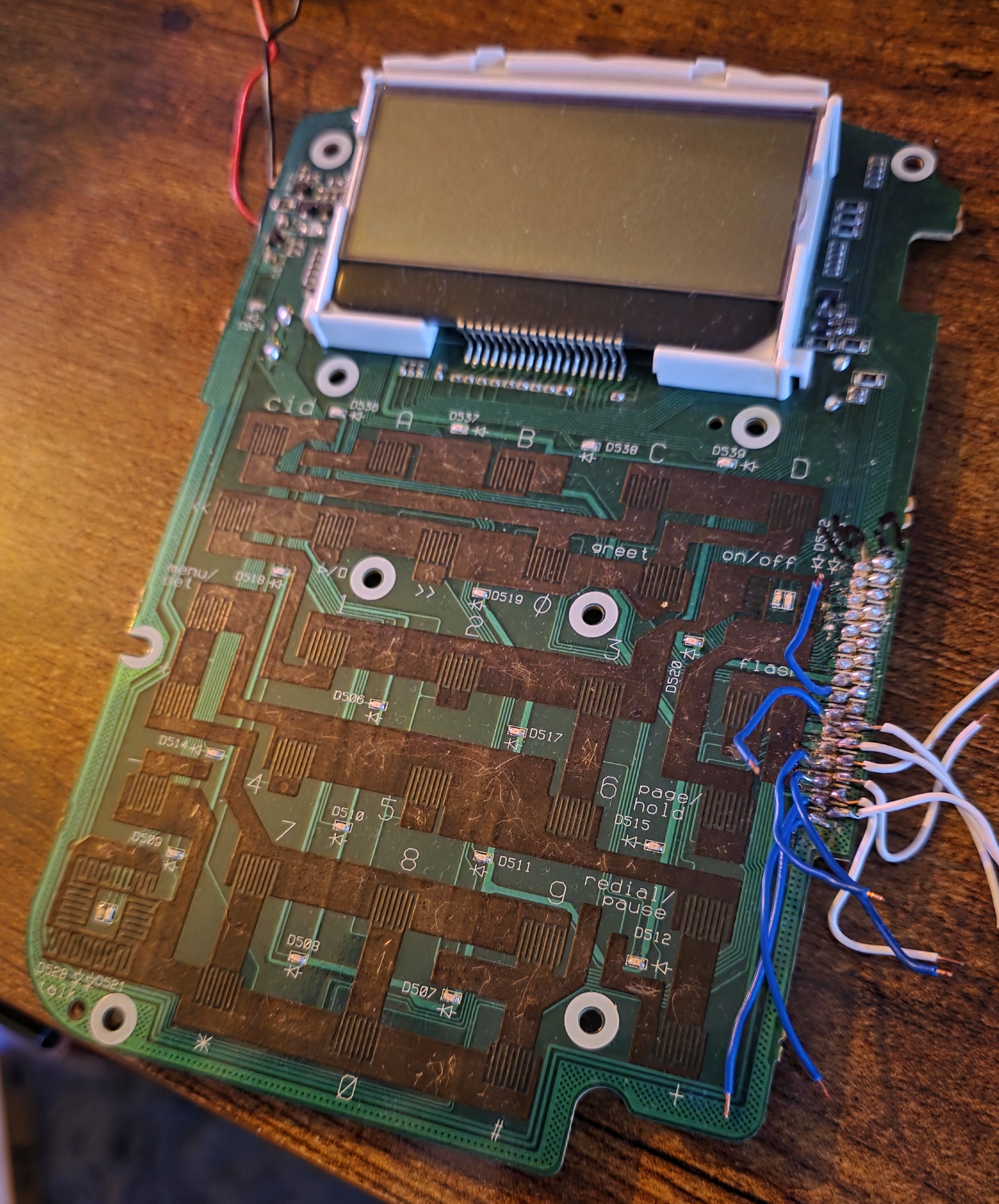
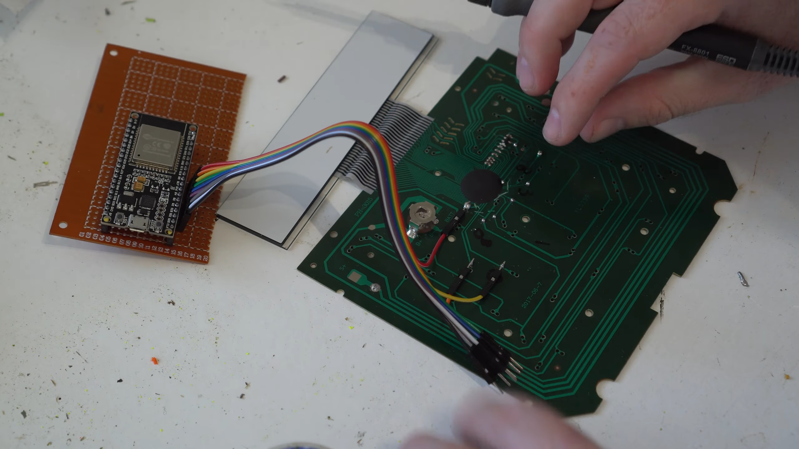
Generally, you’ll also find all the traces lead back to some main chip or connector, where you can easily solder on leads to hook up your own microcontroller to read all the buttons. It’s not always this easy—some boards will help you out with accessible test pads, while others will only provide tiny solder points for fine pitch connectors. In a worst case scenario, you might have to scrape solder resist off some traces so you can solder your wires in that way.
Once you’ve got a microcontroller hooked up to your button pads, the hard part is over. You just need to write some simple code to scan the key matrix and detect button presses. You can use a pre-baked library if you so desire, or you can do it yourself. Ultimately, a simple way is to just energize a row with an output I/O pin while setting all the column pins to inputs to see if any buttons are currently pressed, and stepping through the rows from there. You can get fancier about it if you like if things like latency or anti-ghosting are critical to you, but that’s a discussion for another time. With the high clock speeds of modern microcontrollers, it’s trivial to read even a large key matrix at a rapid pace.
Figuring out how to interface button pads on random hardware is a fun hacking skill to learn, and is accessible for beginners.
It’s worth noting that you might also have to cut some traces going to components of the original circuit, depending on what you’re hacking on. Oftentimes it’s not necessary, particularly if you’re unfussed what happens to any original circuitry on the board. For example, if you do intend to restore the item you’re hacking to original function, it might not be good to be probing the keypad with a 5 V microcontroller when the original hardware all ran at 3.3V. You might hurt the original chips on board if some voltage ends up where you didn’t intend it to go.
If you’ve ever dreamed of turning an air conditioner remote into a secret access panel for your home security system, or making your microwave into a cellular phone, these techniques will serve you well. Go forth, hunt down the matrix, and hack an appliance’s original user interface into the control panel of your dreams.