In the last installment of “The $50 Ham” I built a common tool used by amateur radio operators who are doing any kind of tuning or testing of transmitters: a dummy load. That build resulted in “L’il Dummy”, a small dummy load intended for testing typical VHF-UHF handy talkie (HT) transceivers, screwing directly into the antenna jack on the radio.
As mentioned in the comments by some readers, L’il Dummy has little real utility. There’s actually not much call for a dummy load that screws right into an HT, and it was pointed out that a proper dummy load is commercially available on the cheap. I think the latter observation is missing the point of homebrewing specifically and the Hackaday ethos in general, but I will concede the former point. That’s why at the same time I was building L’il Dummy, I was building the bigger, somewhat more capable version described here: Big Dummy.
Design Goals
As with its smaller HT version, the design for Big Dummy is not completely my own. In the grand tradition of finding what other hams have done and sticking with that, I built a version of a dummy load that K7AGE built, which in turn is a design he borrowed from Elecraft, a maker of kits for transceivers and other ham gear.
My design goals were grander than with L’il Dummy, but still pretty simple. First, I wanted the dummy load to be good for the HF bands and into VHF if possible. Second, it needed to handle more power than L’il Dummy – I was shooting for 50 watts. Third, I wanted it to have a tap for making measurements of transmitter output, and the more standard SO-239 UHF-style connector. And finally, I wanted it to look good.
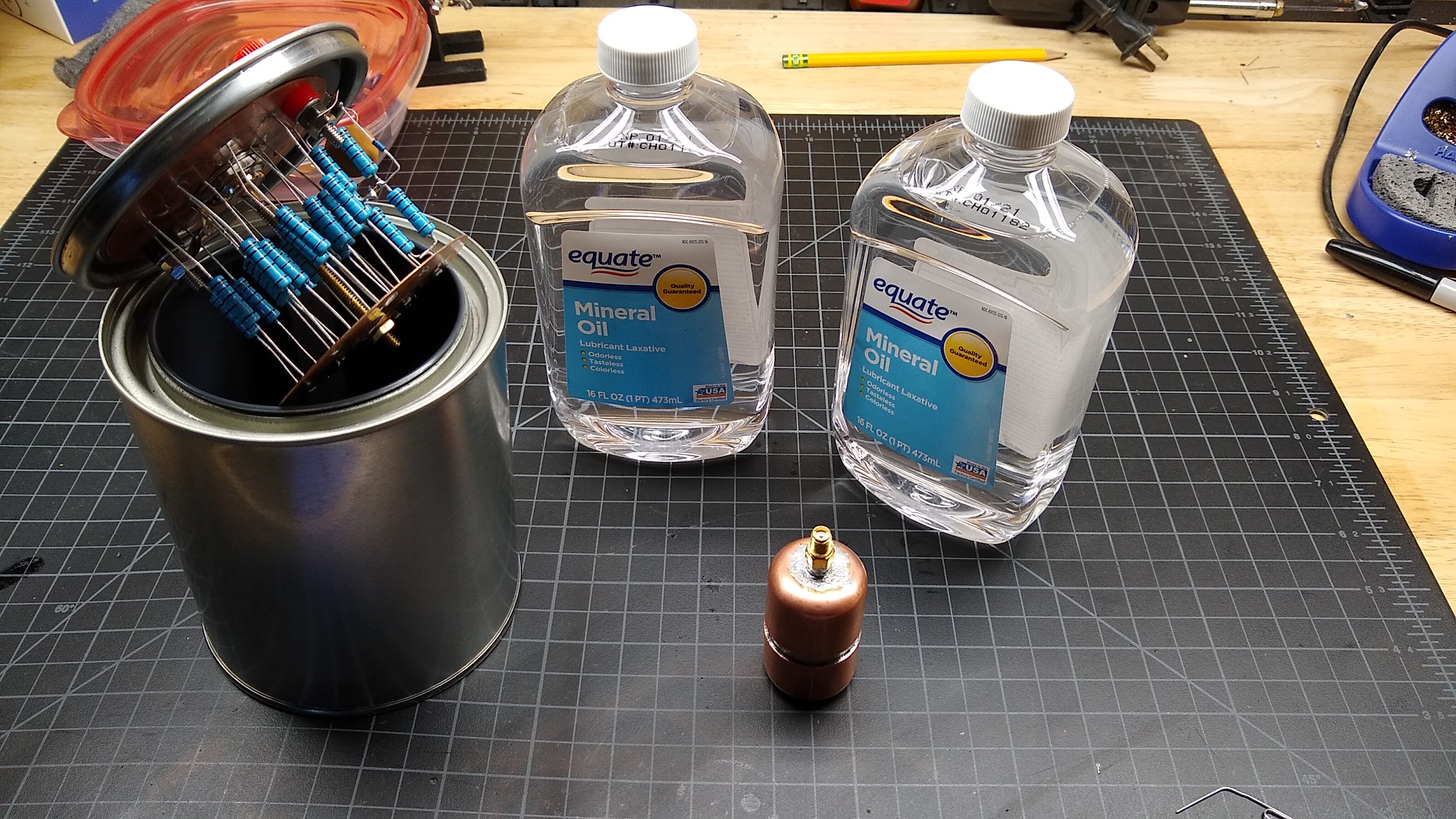
I decided to build a smaller version of the classic “Cantenna” dummy load. Not to be confused with the Pringles-can WiFi antennas we’ve seen plenty of before, a cantenna load is a big 50 Ω resistor in a paint can filled with dielectric oil for cooling. I chose to make mine in a quart (about a liter) paint can.
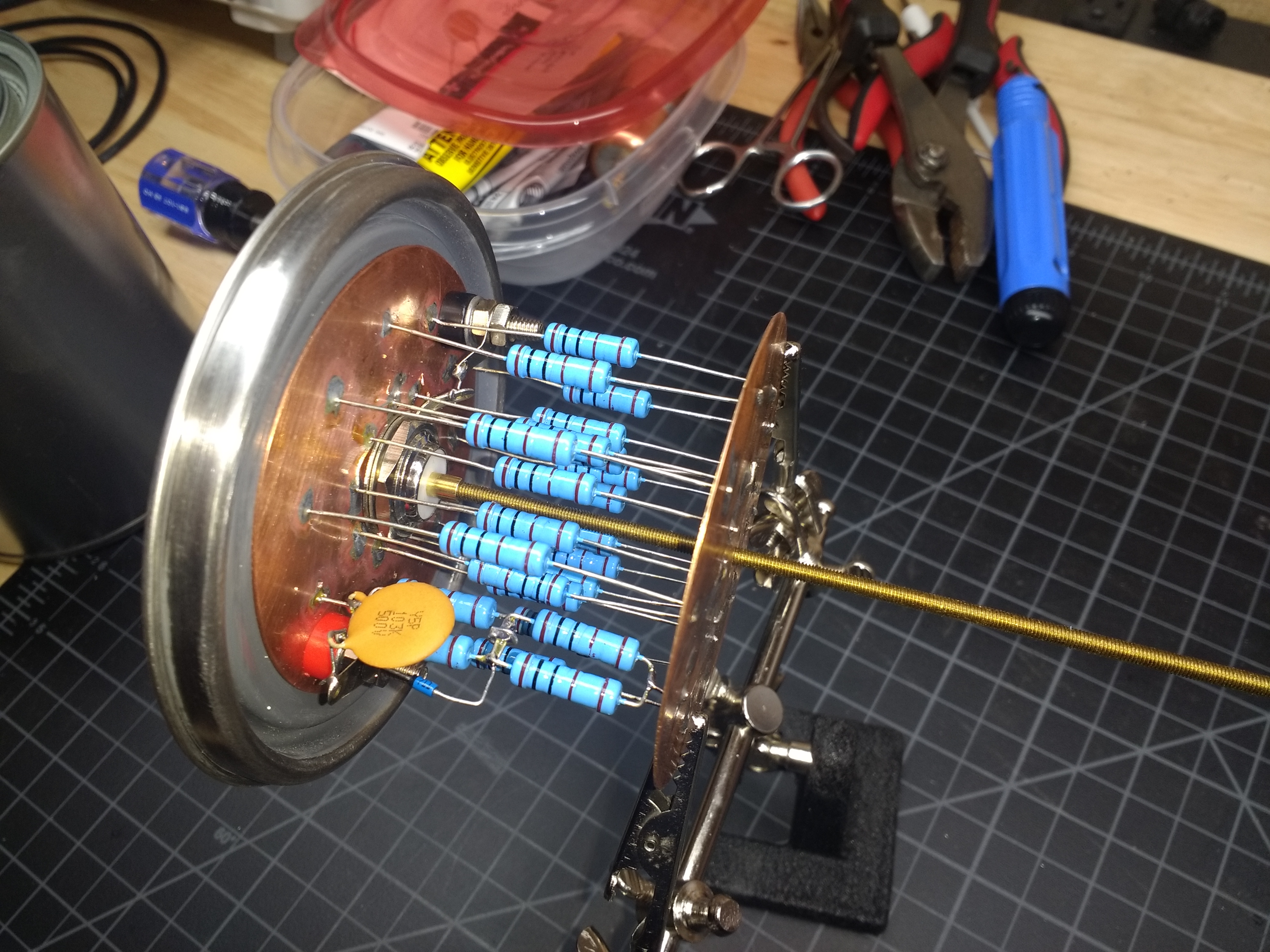
Resistor choice for Big Dummy was a little more difficult than sourcing a single 35 W thick-film SMT resistor was for L’il Dummy. Wirewound power resistors are easy to find, but as previously noted they’re entirely wrong for a dummy load, as their inductance would change the impedance of the load at higher frequencies. I finally managed to find 1000 Ω metal-film resistors in traditional axial lead packages. A pack of 30 only cost me a few bucks. The plan was to put twenty 1000 Ω resistors in parallel, resulting in a total impedance of 50 Ω. At two watts dissipation each, that should make the load capable of handling 40 W – close enough to my target 50 W.
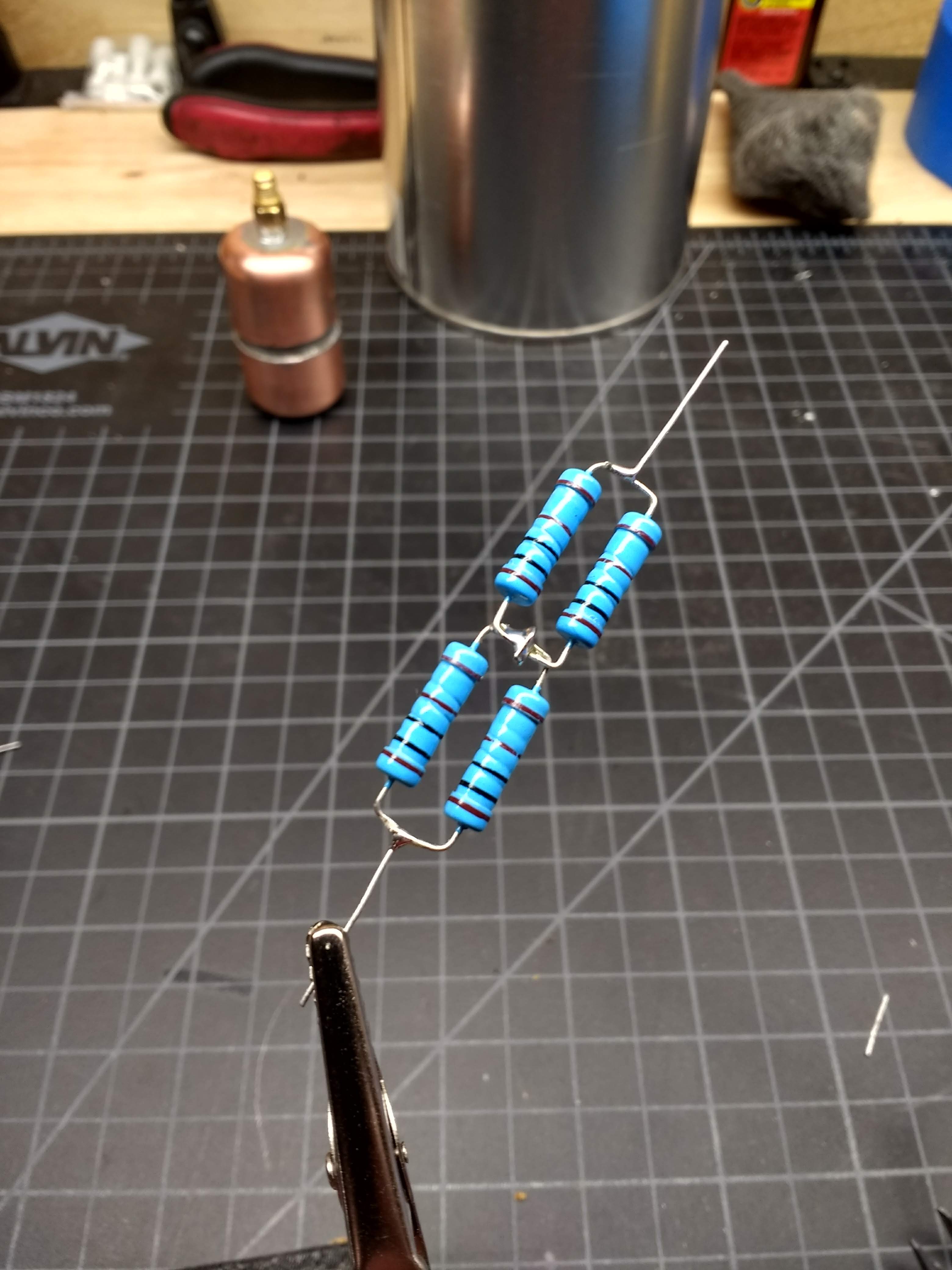
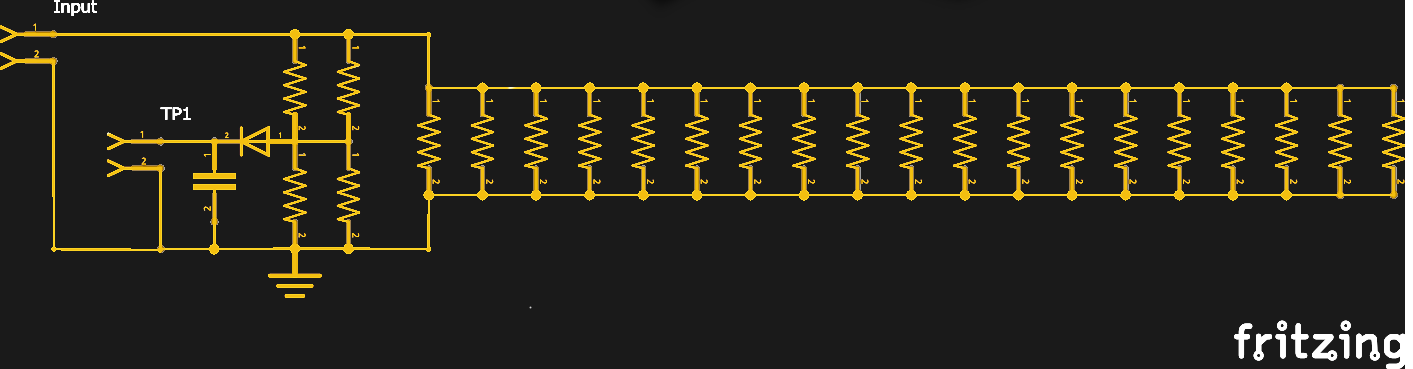
The tap for the test point was a modification on K7AGE’s design as well. He used a series-parallel network to build his dummy load, which gave him a natural tap point between two of the series resistors that acts as a voltage divider. I had to play a few tricks with the resistors I had to make up a network that does the same thing. I detail its construction in my Hackaday.io post, but the quick version is that four 1 kΩ resistors in a parallel-series arrangement did the trick, allowing me to install a 1N5711 Schottky diode and a small ceramic decoupling cap for the test point while maintaining an overall 50 Ω load.
The Build
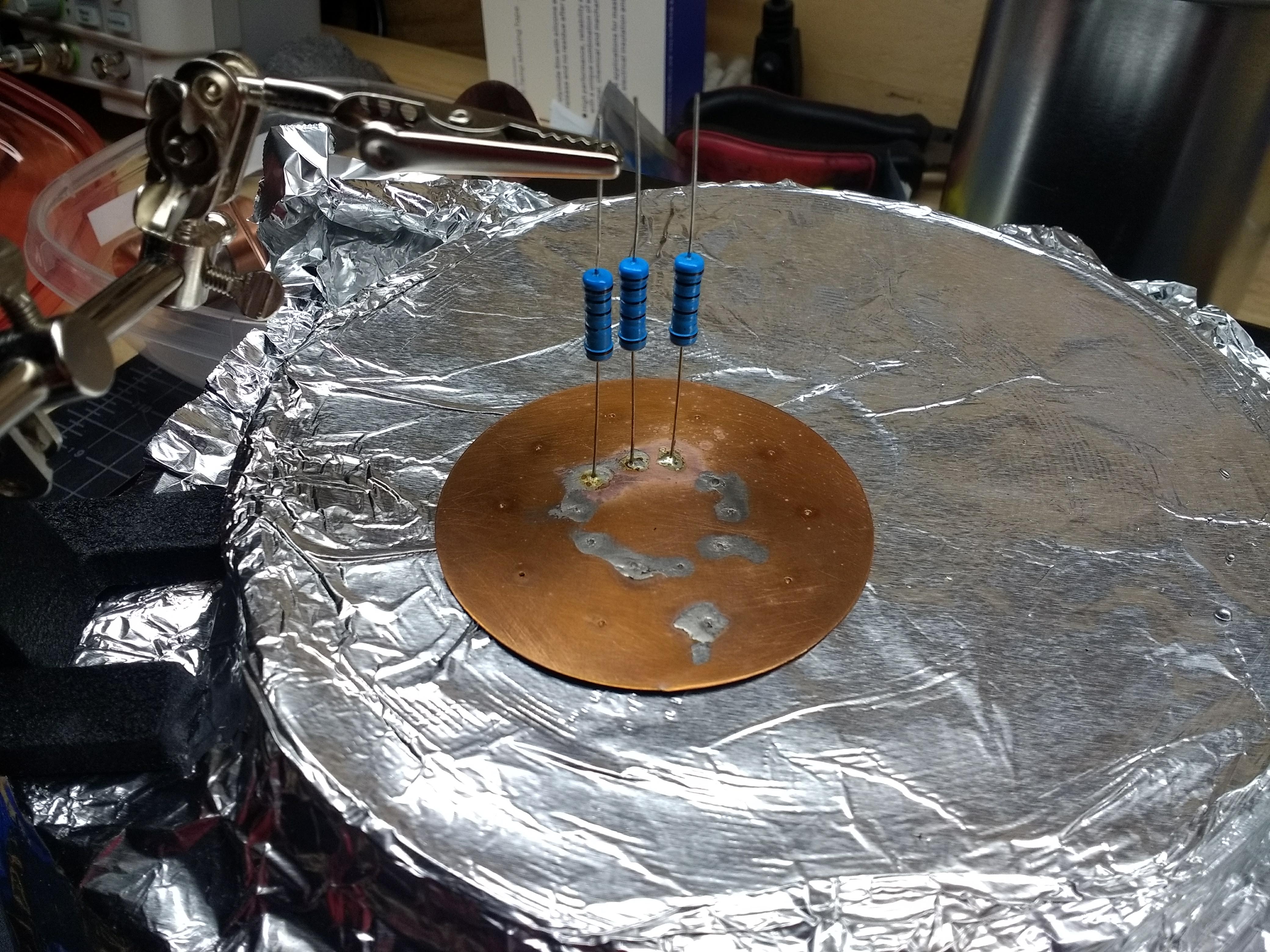
To keep stray inductance at bay, I decided to mount the resistors between two copper discs. This sounded like a way better idea than it turned out to be. I’ll leave the hijinks that resulted from that decision to the build log, but suffice it to say that trying to solder twenty resistors to a heavy copper plate is not as easy as you might think. I ended up using a cheap hot plate to heat the whole assembly evenly and soldering all the leads to one plate at the same time, then flipping the assembly over and doing it again.
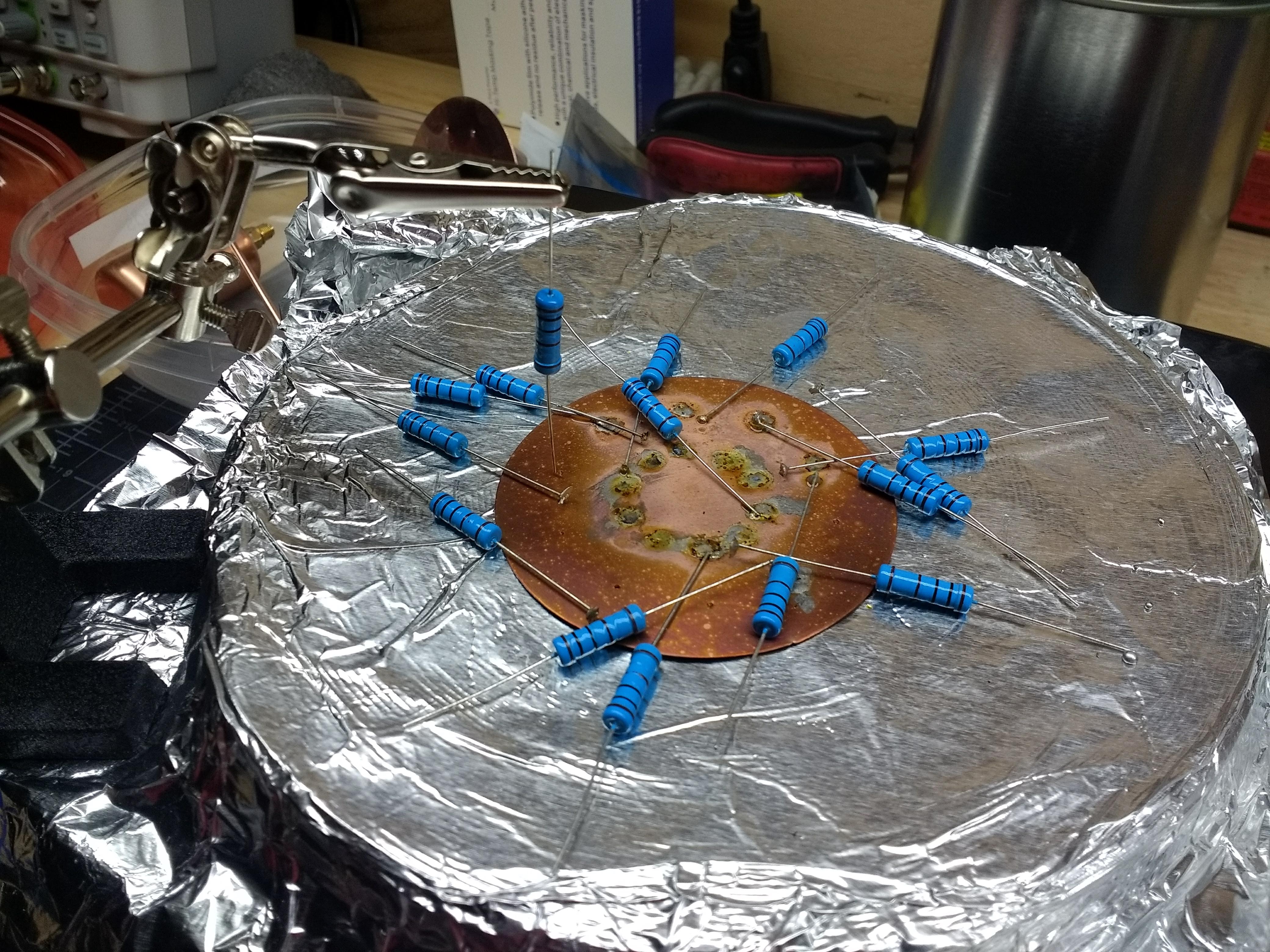
I finally figured out how to do it – the plates needed to be held together with threaded rod first, and I needed to use holes rather than dimples in the copper plates. That resulted in this beauty of overkill – I really dig circuit sculptures, and I wanted it to look good before taking a dunk.
Finishing Up
I chose plain mineral oil for my dielectric fluid. I was warned that oil-filled dummy loads always end up making a mess, but I decided to try it anyway. It took most of a liter of oil to fill the can, and I did get some initial leaking around the connectors penetrating the top of the can. I may have to add gaskets on some kind, but it’s fine for now if I just keep it upright.
I did the exact same test described in my last post to determine how flat the impedance of Big Dummy is across the range from 2.5 MHz to 20 MHz, the upper limit of my function generator. The data was almost identical to the readings from L’il Dummy, meaning this load is a flat 50 Ω across the ham HF bands. Unfortunately, I haven’t pulled my HF rig out of storage yet since moving across the country, so testing at full power and making some measurements using the test points will have to wait.
Next Time
I think I’ve really caught the homebrewing bug with these two builds, so I’m going to look for another cheap build to do for next time. I’m leaning toward characterizing the notoriously dirty output of the Baofeng and seeing if there’s a filter we can build to clean it up. If you have any ideas on that, please sound off below.